
Photographing for 3D Lenticular

This Article was featured in Stereoscopy Magazine Number 103
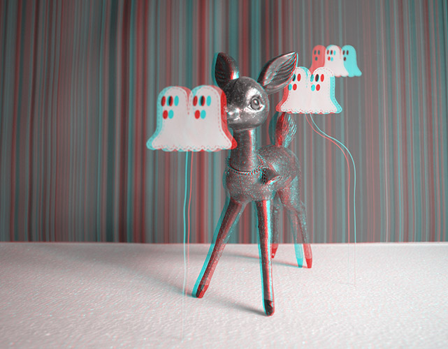
There are several ways to create the illusion of three dimensions using the lenticular process but one of the most effective has always been natural 3D photography. What follows is a basic workflow for creating image sequences optimized for lenticular printing using a single camera. It primarily addresses a controlled studio environment with a camera/rail system but many of the principles apply to multi camera rigs as well. Use of Red/Cyan anaglyph 3D glasses is recommended in parts.
The Single Camera Rail System
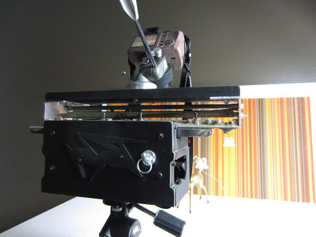
Rail systems are commercially available or can be easily constructed. Manually operated sliders are the most common but a growing number of options exist for inexpensive motorized systems including our very own DIY camera slider! The length of the rail determines the maximum stereo base and should be related to the kinds of subjects and situations being photographed with 24" being sufficient for most studio situations. This example uses a vintage wide carriage typewriter that has been modified and fit with a tripod mount. The camera is carried past the subject in 1/12” increments using a lever to trigger the space bar mechanism.
Scene Construction
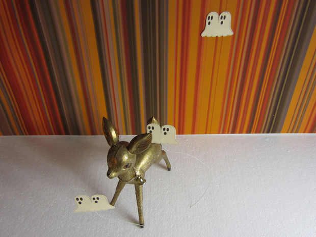
Both two image stereoscopic and multi image lenticular benefit from intentional scene construction when possible. The following strengthen the 3D effect:
- Keep the subject close to the background and use as shallow a space as possible. Minimizing empty space allows the subject to be the primary recipient of the 3D effect and not the area around it. This also contributes to a volumetric 3D quality.
- Avoid single flat colors for the background. Non detailed backgrounds do not register as depth.
- Use occluding objects. Having objects overlap gives the depth effect more points of reference and makes it stronger.
- Watch the edges of the compositional frame, especially the sides. If an object close to the camera comes in from the side of the frame, like a tree branch, it may create a stereo window violation in the print and limit options later on. Foreground objects should not touch or run through either side of the frame. This can also be said for the top and bottom of the compositional frame, but it is less problematic in these areas.
Shooting the Scene
Shooting for lenticular has the same concerns as traditional photography and a few of its own.
- Stereobase. A common rule of thumb when shooting stereo pairs involves moving the camera horizontally 1/30th the distance measured from the camera to the nearest subject in a scene. Lenticular's optics require roughly 3x more stereobase than traditional stereo shooting, effectively giving us a 1/10th rule. If the subject is 10 feet away you should estimate a one foot stereobase.
- Camera Movement and shooting. Its best to move the camera from left to right along the rail. This creates a sequence of images that will be in the order most commonly rendered by software and familiar to lenticular printing services. The exact number of photos needed is determined by the resolution of the output printer's print head (DPI) and the lines per inch (LPI) of the lens, where DPI divided by LPI equals the optimal number of images. With Epson printers and popular 3D lenses this number is usually 18 or 36 and it may be best to assume 36 images for most shoots since it allows for flexibility down the road.
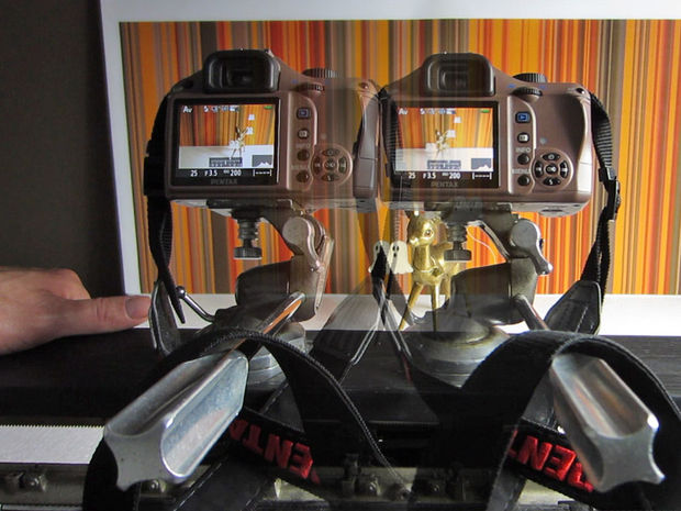
The question of whether to toe-in the camera as it moves along the rail in an effort to keep the subject in the center is often debated, and many professional rigs have such a pre-selected point of convergence. The advantage is that you crop many fewer pixels from the final image and can easily create landscape oriented prints. The disadvantages involve an additional layer of technical effort and unwanted vertical parallax in the scene. For the purpose of simplicity the focus here is single direction parallel shooting.
- Depth of Field. If the equipment and aesthetic considerations allow it, use a large aperture for a shallow depth of field. When background and extreme close objects are blurry a larger stereobase can be used for a greater 3D effect and there is less jump between frames in the areas of deepest 3D.
- Focusing. Move the camera along the rail until it is directly in front of the subject and focus the lens. Then turn the Auto Focus off. Since you will be sliding the camera through the scene it may choose to focus on background details and leave a blurry subject.
SETTING THE POINT OF CONVERGENCE
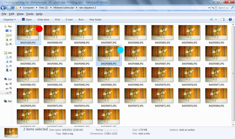
After the images have been taken it is perhaps easiest to evaluate the 3D qualities by creating an anaglyph from two images taken from the sequence. StereoPhoto Maker is an excellent free program for working with stereoscopic and lenticular images and can be used to quickly make anaglyph images and much more. However the workflow Photoshop is fairly straight forward too. To make an anaglyph from a 36 image sequence in Photoshop:
- Open two images 12 frames apart in the sequence. Twelve frames is 1/3 of a 36 image sequence (obvious but important) and 1/3 of a properly shot lenticular sequence should yield an optimal two image stereoscopic pair. Copy the Right image and paste it over the Left.
- Desaturate both layers: Image/Adjustments/Desaturate
- Right Click the top layer: Blending Options/Advanced Blending/ uncheck the Red channel. The bottom layer is left alone.
The left and right images now need to be aligned like any stereo pair:
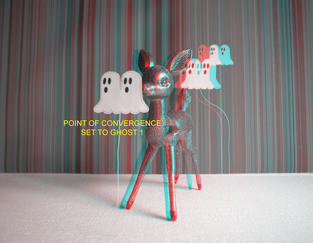
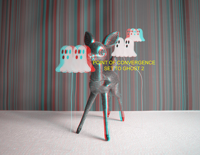
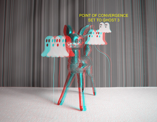
Put on the 3D glasses and move the top layer horizontally until things begin to overlap - this will affect the point of convergence. If at all possible you should have objects that both project toward the viewer and recede into the background to maximize the depth effect. Play with different points of convergence until you find a position that balances the foreground and background depth in a way that is pleasing to you, aiming to have roughly 2x more background parallax than foreground. Unlike traditional stereo imagery that appears sharp from front to back lenticular prints have a depth of field softening on extreme foreground and background areas. The point of convergence will always be the area of greatest clarity in the print.
Measuring Scene Parallax
1. Once you have determined a reasonable point of convergence (details on the fawns face make a balanced point of convergence in the sample) it is time to see how much total parallax the scene has. Select frames 1 and 36 and align these images at the point of convergence chosen in the previous step. You will not be able to do this wearing glasses, the images are too far apart, so simply make the top layer 50% opaque so you can see the layer below.
2. Crop the image to its final proportions and make it the size you intend to print. You can leave Resample unchecked – there is no need to change the actual pixel values, just the values in inches or cm. This important step must be done before proceeding, knowing your final print size is critical for creating an optimal effect.
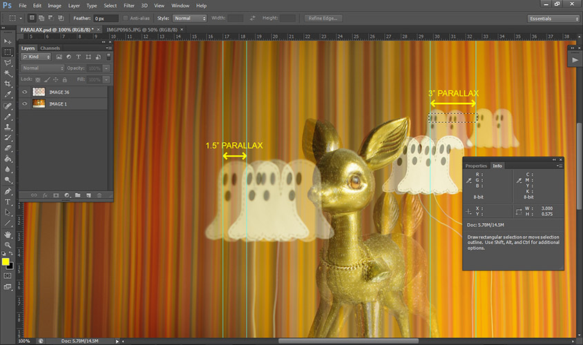
3. Take some measurements. In the closest foreground and farthest background areas find an element in each that is prominent, something easily seen in both the right and left layers. In the sample photos the eyes on the front and rear ghost make good objects to measure. To Measure:
A) Change the rulers in Photoshop to display inches
B) Open the Info window
C) Using the Marquee tool drag a rectangle between the prominent background element as it appears in both the left and right layers. The Info window will show the total width. This is the rear (positive) parallax of the stereoscopic scene. Do the same to find the forward (negative) parallax.
Parallax Goals
1. With lenticular prints the concern is to target a fixed amount of parallax based on the requirements of the lens being used. A starting point should consider 3" for a 20 LPI lens and 1.5" for a 40 LPI lens to be desirable parallax values. These are popular 3D lenses, the finer 3D 40 LPI lens is typically used for images 12x12" and larger and the 3D 20 LPI lens for images over 24x24".
Parallax is image dependent and can be manipulated. It is possible to use greater parallax if the deep parts of the image are significantly blurry. Or less can be used if there are fine details that need to be preserved like text or thin lines. These values refer to the background areas. For the foreground the parallax values should be roughly half.
2. If the parallax values for the image are not close to those being discussed try moving the point of convergence by nudging the top layer to the left or right. If the net parallax is too large find a new pair of images in the sequence with better results, reduce the stereobase based on this information and reshoot. If it is too little reshoot the sequence with a larger stereo base.
Aligning the Sequence
Align all of the images to the point of convergence. A great workflow for aligning images exists using the “Multiple Images” feature in StereoPhoto Maker and is recommended. The concept is simple, however, and can be easily done in Photoshop.
1. Make a single layered PSD from the sequence. File/Scripts/Load Files into Stack
2. Hide all but the bottom layer and pull guidelines from the top and side rulers and place them at the desired point of convergence.
3. One by one align each of the layers to these guidelines
4. Noting that there are now empty areas in the image canvas on the sides and possibly the top and bottom. Crop the image to it largest dimensions.
5. Create a new folder and Export layers as files: Files/Scripts/Export Layers to Files
Print Considerations
With a lenticular sequence in hand you are ready to make prints. While detailed steps for producing output are not discussed here a few considerations are worth keeping in mind. The 36 image sequence made using the steps above will work on variety of printers but the parallax values and image count is optimized for laminated inkjet output on a piezo printer (Epson, Mimaki, Mutoh, etc.) These printers are common among lenticular printing services because of their precise dot placement and resolution and the two step laminated method is preferred for high quality, low volume production. Other options include flatbed UV printing (billboards, outdoor images), offset printing (high quantity, smaller size) and photographic processes like Lightjet and Lambda (color dense images for backlighting). For the best results parallax and image counts should be discussed with the printer in advance.